

Here, Bill Eccles from Bolt Science, looks at how to know for sure which bolt is the right size for each unique joint interface, and whether a smaller bolt could be used without risking the integrity of the bolt/joint.
Joint diagrams can display a significant amount of information about the joint but in our experience many people find them difficult to interpret and understand. Preload requirement charts are a way to graphically display the results of a joint analysis in a clear and understandable manner.
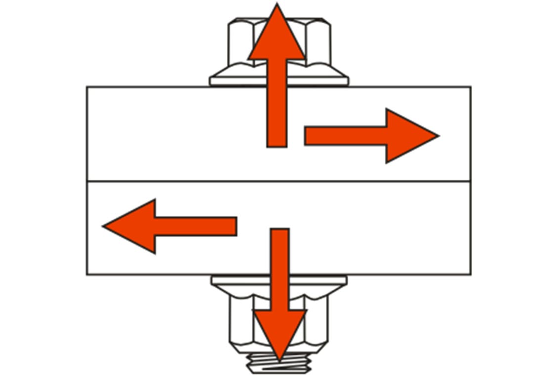
By way of example, consider the joint shown below that is subject to combined axial and shear loading. For information, the bolt is M12 property Class 10.9, the joint thickness is 20mm with an axial load of 15kN and a shear force of 4kN being applied. (If the joint consists of several bolts, it is first necessary to determine the loading on an individual bolt.)
One key aspect to appreciate is that the root cause of the majority of bolt/joint failures is due to insufficient preload. It is unusual for the bolt to be overloaded. If the preload provided by the bolt is insufficient, joint separation and movement can occur resulting in possible bolt fatigue and self-loosening issues.
In order that such problems do not occur it is vital that there is sufficient residual clamp force acting on the joint interface after accounting for the effects of the applied forces and embedding losses. A Preload Requirement Chart graphically illustrates this point as it looks at the forces acting on the joint interface. Such a chart is shown below for the above joint.
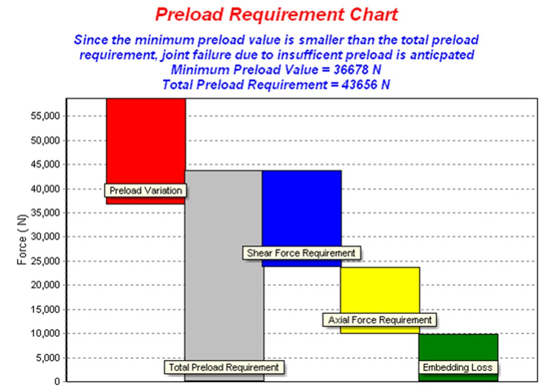
The above chart was produced by the BOLTCALC program, but such charts can be produced manually.
Explaining each of the parts of the chart in turn:
Embedding loss
Embedding is localised plastic deformation that occurs under the nut face, in the joint faces and in the threads as a result of flattening of the surface roughness. Embedding results in a loss of clamp force acting on the joint.
If the joint and bolt stiffness can be established, the amount of this force loss can be quantified if the surface roughness of the contact surfaces is defined. In the above chart, a loss of 10kN is anticipated. Large amounts of embedding loss can occur in joints with a short grip length consisting of many interfaces.
Axial force requirement:
In a preloaded joint, the majority of the applied axial load reduces the clamp force on the joint interface rather than increasing the load in the bolt. The amount of the axial load that unloads the joint interface can be determined from the joint/bolt stiffness calculations.
In this example, of the 15kN applied force, 13.8kN reduces the clamp force on the interface (the remaining 1.2kN increases the load in the bolt). To simplify, when hand calculations are being completed, the conservative assumption is often applied that all the applied axial load reduces the clamp force on the joint interface.
Shear force requirement
The majority of joints in mechanical engineering use clearance holes and any shear load is transmitted by friction grip. That is, the clamp force on the joint interface generates a friction force that resists any applied shear loading. On such joints, if slippage is prevented, the bolts do not directly sustain any shear loading, however they have to provide sufficient clamp force to prevent joint movement.
To achieve this, the clamp force required is the shear force divided by the coefficient of friction present between the joint surfaces (for the single shear plane present in the joint shown above). Since the coefficient of friction is usually significantly less than 1, this requirement results in a significantly larger clamp force being required than the magnitude of the shear force. In this example, the applied shear is 4kN which, if a coefficient of friction of 0.2 is assumed between the joint plates, results in a minimum clamp force of 20kN (i.e. 4/0.2).
Total preload requirement
This represents the minimum preload required to be provided by the bolt. It is the sum of the embedding loss, the amount of the applied axial force that reduces the clamp force on the joint and the clamp force needed to prevent slippage of the joint due to a shear loading.
Preload variation
In an ideal world the preload provided by the bolt would be known to an exact value and would be the same for every bolt tightened. Unfortunately there is no low cost means of tightening a bolt and knowing, precisely, the preload value.
Techniques such as tightening the bolt to a specific torque value results in variation in the preload between, apparently, identical bolts. This is as a result of not being able to apply the torque to the same exact value each time, variation in the hole and bolt tolerances but more importantly, variation in the coefficient of friction present in the threads and under the nut/bolt face.
To design a joint successfully this scatter in the preload must be taken into account. This can be done in a number of ways but usually either by determining the minimum/maximum preloads from knowledge of the friction variation or by the use of a tightening factor.
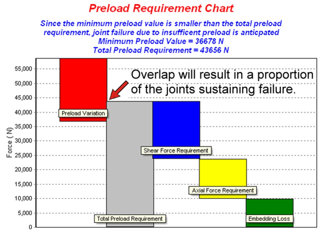
The problem
In the above chart the total preload requirement exceeds the minimum preload. What this means is that on some, but not all joints, the preload will be insufficient to resist the applied forces. In such cases, joint failure can be anticipated.
The failure is likely to be by either bolt fatigue (due to bending due to the joint slipping and separating) or by self-loosening (due to joint movement).
The solution
In general, changes can be made to increase the minimum preload value (by using a stronger or larger bolt or changing the tightening method) or by reducing the applied forces (by using more bolts in the joint, or by increasing the friction between the joint interface and so reducing the shear force requirement etc.)
Shown below is the chart for changing the tightening method to torque and angle. If applied correctly this method will consistently provide a high preload value.

Factor of safety
A question which often arises is how much of a gap there should be between the total preload requirement and the minimum preload value. In mechanical engineering in which there are generally no design codes to stipulate the factor of safety, this depends essentially upon engineering judgement.
If the applied forces are accurately known, if product testing is going to be completed, then the gap can be small. If the forces are not known accurately, and the consequences of failure disastrous, then a larger gap would be sensible. The consequence of having a generous factor of safety is that a larger bolt size (or higher strength bolt or better tightening method etc.) would be needed then which would otherwise be the case. This can result in a more expensive and less competitive product.

Preload requirement charts can be developed to include other effects such as the effect on bolt loading of differential thermal expansion. They are a useful method for joint analysis and solving bolting issues.